LM136-5.0/LM236-5.0/LM336-5.0
5.0V Reference Diode
General Description
The LM136-5.0/LM236-5.0/LM336-5.0 integrated circuits are
precision 5.0V shunt regulator diodes. These monolithic IC
voltage references operate as a low temperature coefficient
5.0V zener with 0.6
dynamic impedance. A third terminal
on the LM136-5.0 allows the reference voltage and tempera-
ture coefficient to be trimmed easily.
The LM136-5.0 series is useful as a precision 5.0V low volt-
age reference for digital voltmeters, power supplies or op
amp circuitry. The 5.0V makes it convenient to obtain a
stable reference from low voltage supplies. Further, since
the LM136-5.0 operates as a shunt regulator, it can be used
as either a positive or negative voltage reference.
The LM136-5.0 is rated for operation over -55įC to +125įC
while the LM236-5.0 is rated over a -25įC to +85įC tem-
perature range. The LM336-5.0 is rated for operation over a
0įC to +70įC temperature range. See the connection dia-
grams for available packages. For applications requiring
2.5V see LM136-2.5.
Features
n
Adjustable 4V to 6V
n
Low temperature coefficient
n
Wide operating current of 600 ĶA to 10 mA
n
0.6
dynamic impedance
n
Ī
1% initial tolerance available
n
Guaranteed temperature stability
n
Easily trimmed for minimum temperature drift
n
Fast turn-on
n
Three lead transistor package
Connection Diagrams
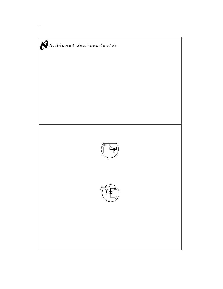
TO-92
Plastic Package
DS005716-4
Bottom View
Order Number LM236AZ-5.0, LM336Z-5.0 or LM336BZ-5.0
See NS Package Number Z03A
TO-46
Metal Can Package
DS005716-5
Bottom View
Order Number LM136H-5.0,
LM136H-5.0/883, LM236H-5.0,
LM136AH-5.0, LM136AH-5.0/883,
or LM236AH-5.0
See NS Package Number H03H
June 1999
LM136-5.0/LM236-5.0/LM336-5.0
5.0V
Reference
Diode
© 1999 National Semiconductor Corporation
DS005716
www.national.com
Connection Diagrams
(Continued)
Typical Applications
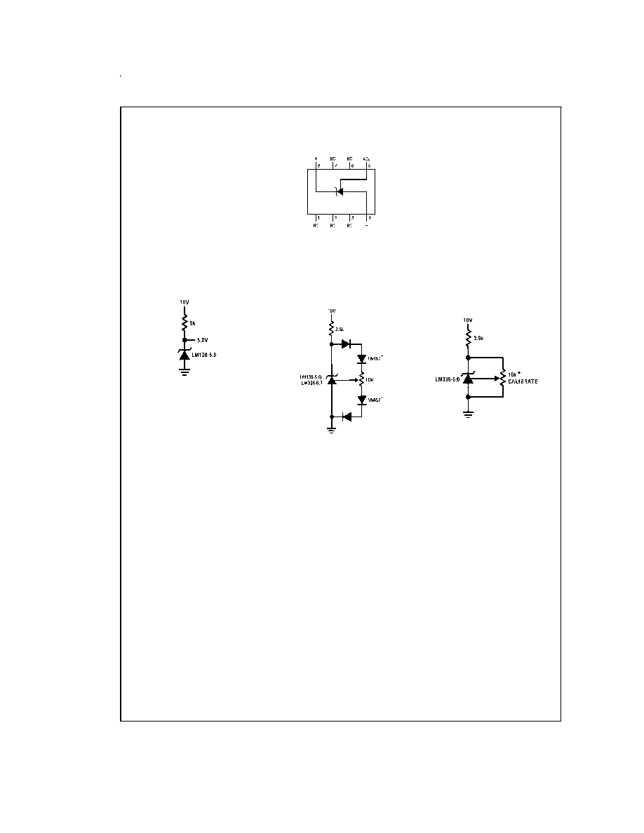
SO Package
DS005716-7
Order Number LM336M-5.0 or LM336BM-5.0
See NS Package Number M08A
5.0V Reference
DS005716-1
5.0V Reference with Minimum
Temperature Coefficient
DS005716-15
Adjust to 5.00V
* Any silicon signal diode
Trimmed 4V to 6V Reference
with Temperature Coefficient
Independent of Breakdown Voltage
DS005716-3
* Does not affect temperature coefficient
www.national.com
2
Absolute Maximum Ratings
(Note 1)
If Military/Aerospace specified devices are required,
please contact the National Semiconductor Sales Office/
Distributors for availability and specifications.
Reverse Current
15mA
Forward Current
10mA
Storage Temperature
-60įC to +150įC
Operating Temperature Range (Note 2)
LM136-5.0
-55įC to +150įC
LM236-5.0
-25įC to +85įC
LM336-5.0
0įC to +70įC
Soldering Information
TO-92 Package (10 sec.)
260įC
TO-46 Package (10 sec.)
300įC
SO Package
Vapor Phase (60 sec.)
215įC
Infrared (15 sec.)
220įC
See AN-450 "Surface Mounting Methods and Their Effect on
Product Reliability" (appendix D) for other methods of solder-
ing surface mount devices.
Electrical Characteristics
(Note 3)
LM136A-5.0/LM236A-5.0
LM336B-5.0
Parameter
Conditions
LM136-5.0/LM236-5.0
LM336-5.0
Units
Min
Typ
Max
Min
Typ
Max
Reverse Breakdown Voltage
T
A
=25įC, I
R
=1 mA
LM136-5.0/LM236-5.0/LM336-5.0
4.9
5.00
5.1
4.8
5.00
5.2
V
LM136A-5.0/LM236A-5.0, LM336B-5.0
4.95
5.00
5.05
4.90
5.00
5.1
V
Reverse Breakdown Change
T
A
=25įC,
6
12
6
20
mV
With Current
600 ĶA
I
R
10 mA
Reverse Dynamic Impedance
T
A
=25įC, I
R
=1 mA, f = 100 Hz
0.6
1.2
0.6
2
Temperature Stability
V
R
Adjusted 5.00V
(Note 4)
I
R
=1 mA, (Figure 2)
0įC
T
A
70įC (LM336-5.0)
4
12
mV
-25įC
T
A
+85įC (LM236-5.0)
7
18
mV
-55įC
T
A
+125įC (LM136-5.0)
20
36
mV
Reverse Breakdown Change
600 ĶA
I
R
10 mA
6
17
6
24
mV
With Current
Adjustment Range
Circuit of
Figure 1
Ī
1
Ī
1
V
Reverse Dynamic Impedance
I
R
= 1 mA
0.8
1.6
0.8
2.5
Long Term Stability
T
A
=25įC
Ī
0.1įC, I
R
=1 mA, t = 1000 hrs
20
20
ppm
Note 1: Absolute Maximum Ratings indicate limits beyond which damage to the device may occur. Electrical specifications do not apply when operating the device
beyond its specified operating conditions.
Note 2: For elevated temperature operation, T
j
max is:
LM136
150įC
LM236
125įC
LM336
100įC
Thermal Resistance
TO-92
TO-46
SO-8
ja
(Junction to Ambient)
180įC/W (0.4" Leads)
440įC/W
165įC/W
170įC/W (0.125"
Leads)
ja
(Junction to Case)
N/A
80įC/W
N/A
Note 3: Unless otherwise specified, the LM136-5.0 is specified from -55įC
T
A
+125įC, the LM236-5.0 from -25įC
T
A
+85įC and the LM336-5.0 from
0įC
T
A
+70įC.
Note 4: Temperature stability for the LM336 and LM236 family is guaranteed by design. Design limits are guaranteed (but not 100% percent production tested) over
the indicated temperature and supply voltage ranges. These limits are not used to calculate outgoing quality levels. Stability is defined as the maximum charge in
V
REF
from 25įC to T
A
(min) or T
A
(max).
www.national.com
3
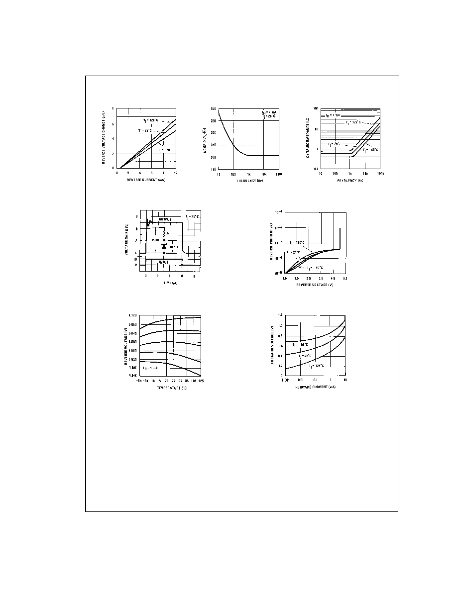
Typical Performance Characteristics
Application Hints
The LM136-5.0 series voltage references are much easier to
use than ordinary zener diodes. Their low impedance and
wide operating current range simplify biasing in almost any
circuit. Further, either the breakdown voltage or the tempera-
ture coefficient can be adjusted to optimize circuit perfor-
mance.
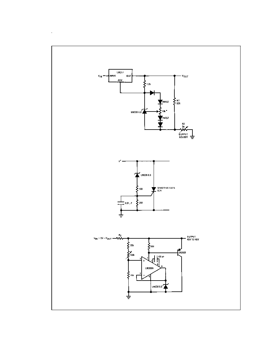
Figure 1 shows an LM136-5.0 with a 10k potentiometer for
adjusting the reverse breakdown voltage. With the addition
of R1 the breakdown voltage can be adjusted without affect-
ing the temperature coefficient of the device. The adjustment
range is usually sufficient to adjust for both the initial device
tolerance and inaccuracies in buffer circuitry.
If minimum temperature coefficient is desired, four diodes
can be added in series with the adjustment potentiometer as
shown in
Figure 2. When the device is adjusted to 5.00V the
temperature coefficient is minimized. Almost any silicon sig-
nal diode can be used for this purpose such as a 1N914,
1N4148 or a 1N457. For proper temperature compensation
the diodes should be in the same thermal environment as
the LM136-5.0. It is usually sufficient to mount the diodes
near the LM136-5.0 on the printed circuit board. The abso-
lute resistance of the network is not critical and any value
from 2k to 20k will work. Because of the wide adjustment
range, fixed resistors should be connected in series with the
pot to make pot setting less critical.
Reverse Voltage Change
DS005716-17
Zener Noise Voltage
DS005716-18
Dynamic Impedance
DS005716-19
Response Time
DS005716-20
Reverse Characteristics
DS005716-21
Temperature Drift
DS005716-22
Forward Characteristics
DS005716-23
www.national.com
4

Application Hints
(Continued)
DS005716-9
FIGURE 1. LM136-5.0 with Pot for Adjustment of
Breakdown Voltage (Trim Range =
Ī
1.0V Typical)
DS005716-10
FIGURE 2. Temperature Coefficient Adjustment
(Trim Range =
Ī
0.5V Typical)
www.national.com
5
Typical Applications
Precision Power Regulator with Low Temperature Coefficient
DS005716-11
* Adjust for 6.25V across R1
5V Crowbar
DS005716-12
Adjustable Shunt Regulator
DS005716-13
www.national.com
6
Typical Applications
(Continued)
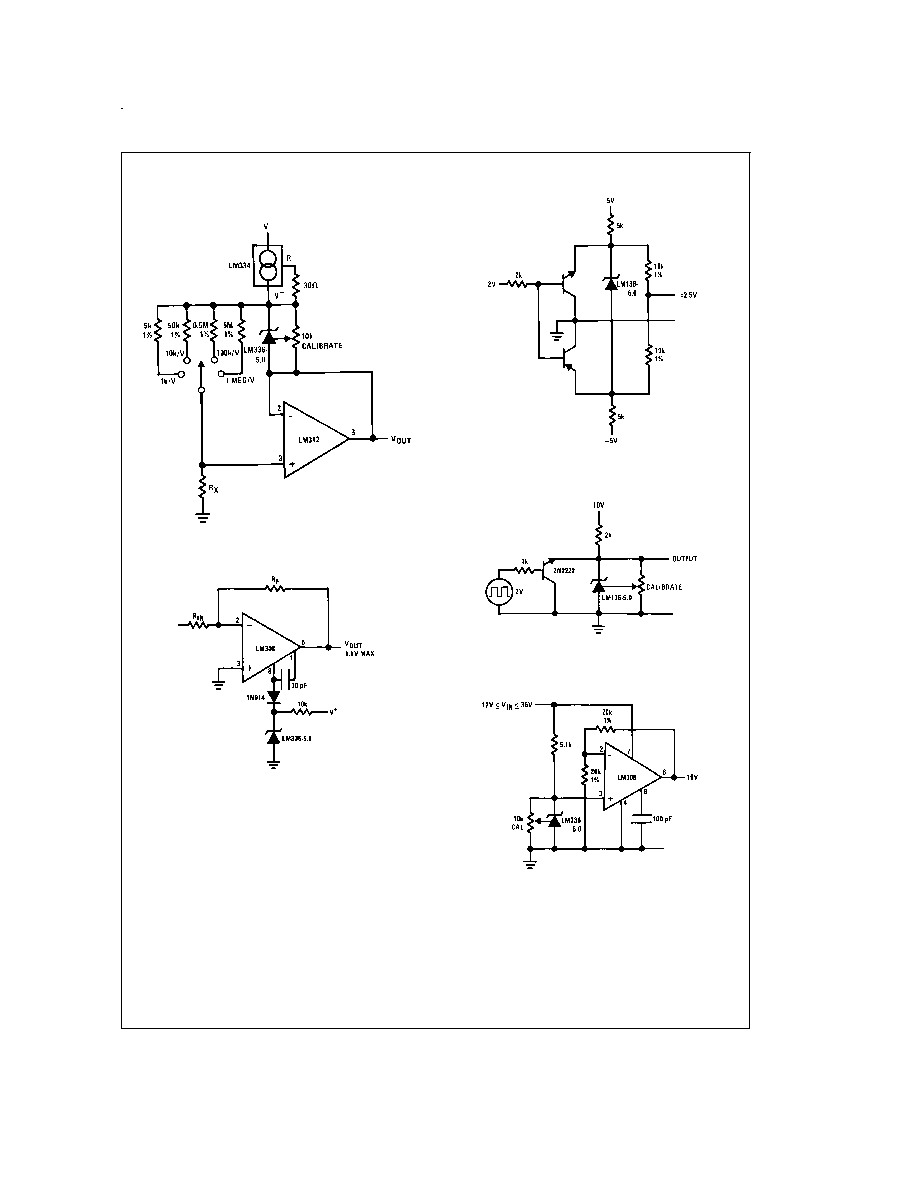
Linear Ohmmeter
DS005716-14
Op Amp with Output Clamped
DS005716-24
Bipolar Output Reference
DS005716-25
5.0V Square Wave Calibrator
DS005716-26
10V Buffered Reference
DS005716-27
www.national.com
7
Typical Applications
(Continued)
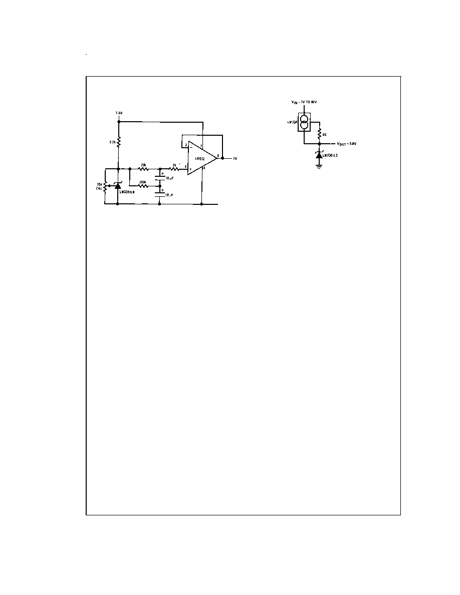
Low Noise Buffered Reference
DS005716-28
Wide Input Range Reference
DS005716-29
www.national.com
8
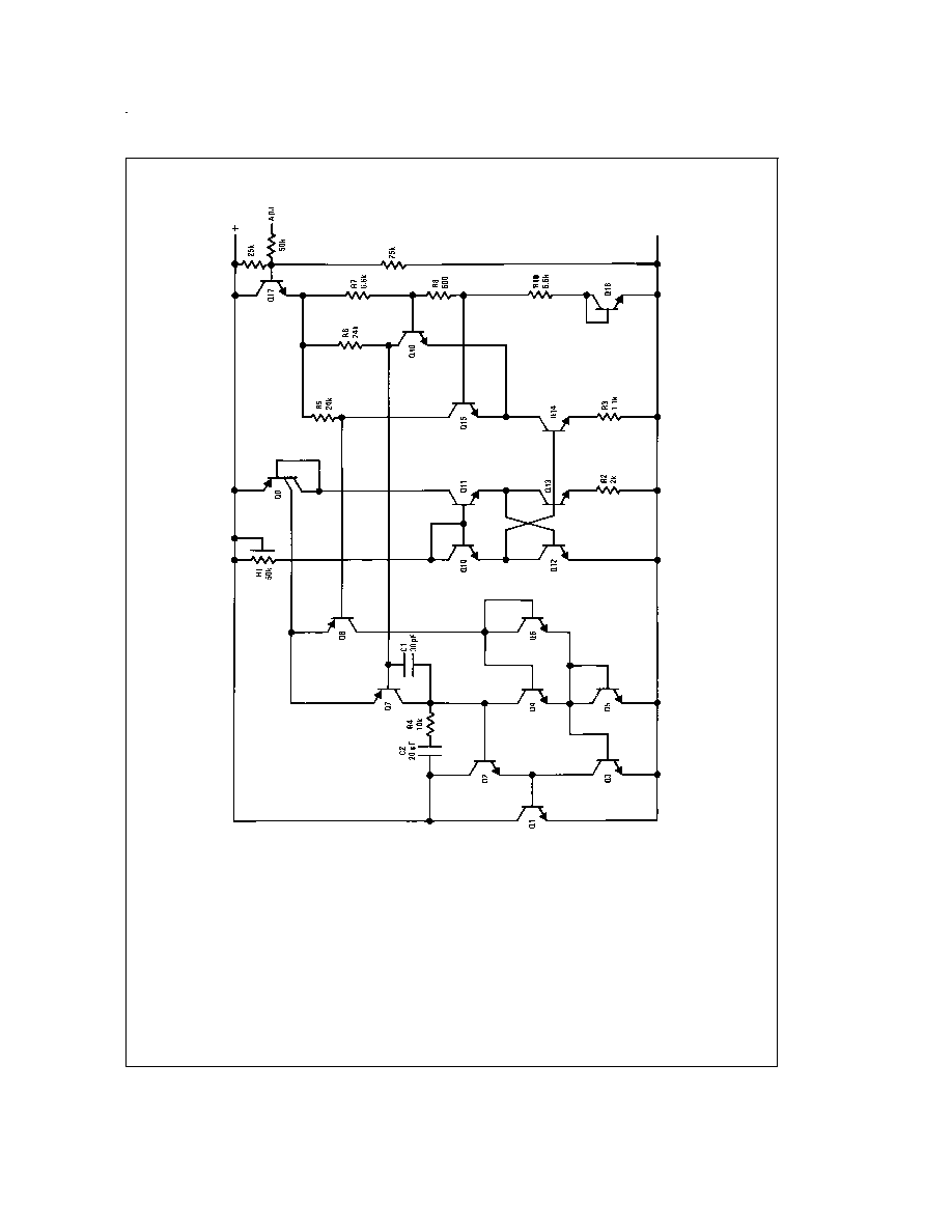
Schematic Diagram
DS005716-16
www.national.com
9
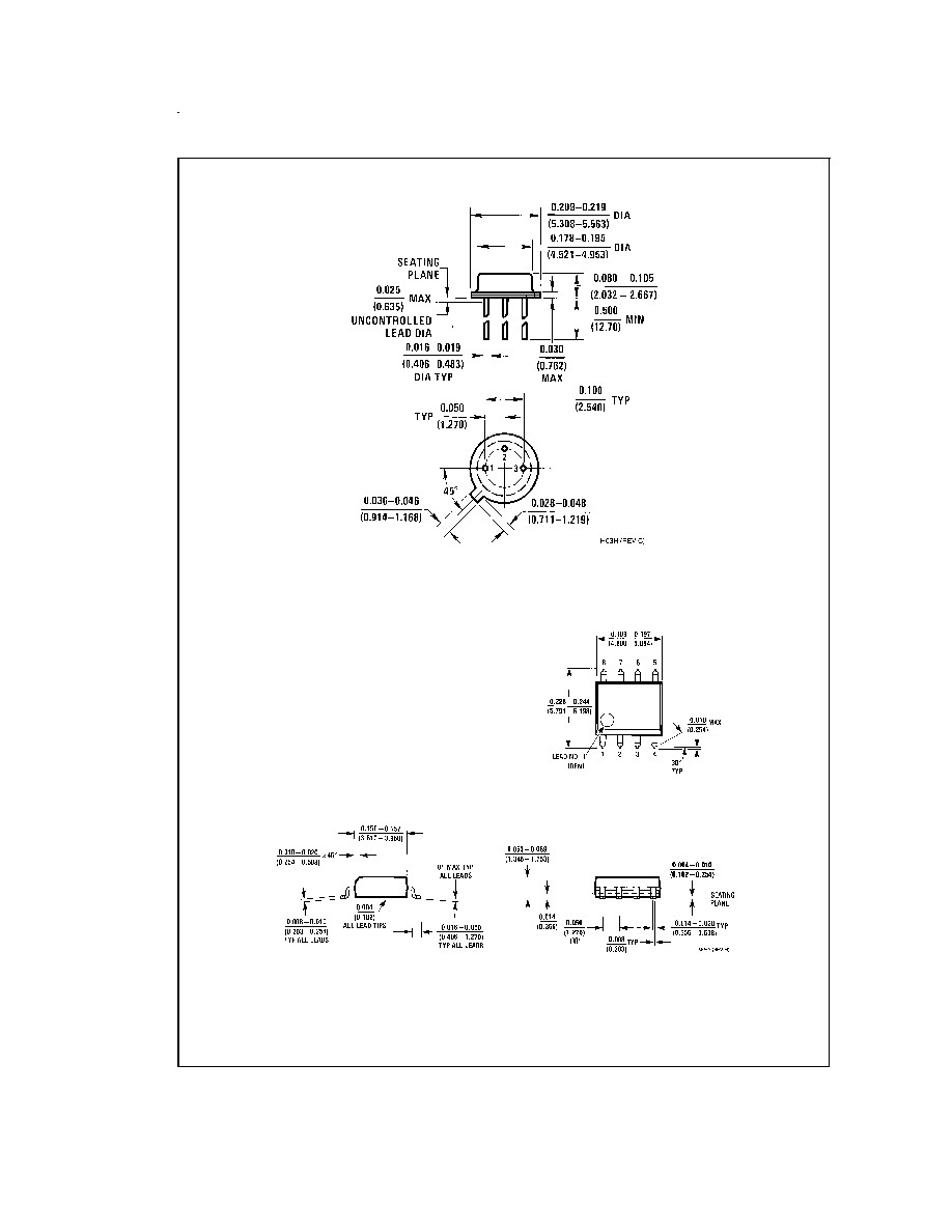
Physical Dimensions
inches (millimeters) unless otherwise noted
TO-46 Metal Can Package (H)
Order Number LM136H-5.0, LM136H-5.0/883, LM236H-5.0,
LM136AH-5.0, LM136AH-5.0/883 or LM236AH-5.0
NS Package Number H03H
Small Outline (SO-8) Package
Order Number LM336M-5.0 or LM336BM-5.0
NS Package Number M08A
www.national.com
10
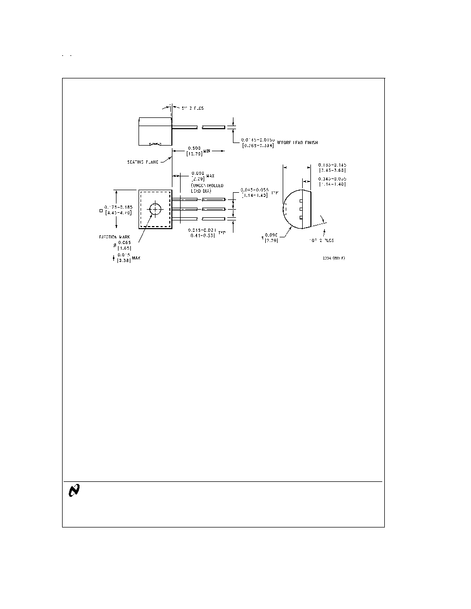
Physical Dimensions
inches (millimeters) unless otherwise noted (Continued)
LIFE SUPPORT POLICY
NATIONAL'S PRODUCTS ARE NOT AUTHORIZED FOR USE AS CRITICAL COMPONENTS IN LIFE SUPPORT
DEVICES OR SYSTEMS WITHOUT THE EXPRESS WRITTEN APPROVAL OF THE PRESIDENT AND GENERAL
COUNSEL OF NATIONAL SEMICONDUCTOR CORPORATION. As used herein:
1. Life support devices or systems are devices or
systems which, (a) are intended for surgical implant
into the body, or (b) support or sustain life, and
whose failure to perform when properly used in
accordance with instructions for use provided in the
labeling, can be reasonably expected to result in a
significant injury to the user.
2. A critical component is any component of a life
support device or system whose failure to perform
can be reasonably expected to cause the failure of
the life support device or system, or to affect its
safety or effectiveness.
National Semiconductor
Corporation
Americas
Tel: 1-800-272-9959
Fax: 1-800-737-7018
Email: support@nsc.com
National Semiconductor
Europe
Fax: +49 (0) 1 80-530 85 86
Email: europe.support@nsc.com
Deutsch Tel: +49 (0) 1 80-530 85 85
English
Tel: +49 (0) 1 80-532 78 32
FranÁais Tel: +49 (0) 1 80-532 93 58
Italiano
Tel: +49 (0) 1 80-534 16 80
National Semiconductor
Asia Pacific Customer
Response Group
Tel: 65-2544466
Fax: 65-2504466
Email: sea.support@nsc.com
National Semiconductor
Japan Ltd.
Tel: 81-3-5639-7560
Fax: 81-3-5639-7507
www.national.com
Plastic Package (Z)
Order Number LM236AZ-5.0, LM336Z-5.0 or LM336BZ-5.0
NS Package Number Z03A
LM136-5.0/LM236-5.0/LM336-5.0
5.0V
Reference
Diode
National does not assume any responsibility for use of any circuitry described, no circuit patent licenses are implied and National reserves the right at any time without notice to change said circuitry and specifications.